
Static Equipment
Spreadsheet Calculators

These calculator tools streamline calculations that are time-consuming to perform by hand, but not so complicated as to require the use of a specialized software. By embedding the relevant formulas, these calculators allow you to enter input data and quickly get the answer you seek. References to the source content are provided in the spreadsheets for all calculations.
Please read this End User Agreement carefully before using the Ingeniare spreadsheet calculators. By using the spreadsheet calculators, you are agreeing to be bound by the terms of this agreement.
(These spreadsheets are in a reserved area so if you are interested in access them you can send us an email to info@ingeniare.net, and we will gladly inform you the cost for one year including consulting hours. Also if you want access for evaluation send us an email to info@ingeniare.net, and we will give you a temporary access for 15 days.)

Atmospheric Tank API STD 650 - Wall Thickness
Spreadsheet calculator following wall thickness calculation methods (5.6) for Atmospheric Tank API STD 650.

Vertical Separator with Flush Inlet Nozzles or Inlet Nozzle with 90° Elbow (Gas - Oil)
Spreadsheet calculator to make process calculation (vessel diameter, vessel longitud, nozzle diameter, liquid level, gas volume, etc).

Horizontal Separator with Inlet Nozzle with 90° Elbow (Gas - Oil)
Spreadsheet calculator to make process calculation (vessel diameter, vessel longitud, nozzle diameter, liquid level, gas volume, etc).

Wall Thickness Calculation of Cylindrical Shells Under Internal Pressure
Spreadsheet calculator as per Section VIII Div 1 - UG 27 - Thickness of Shells Under Internal Pressure.

Wall Thickness Calculation of Conical Section Under Internal Pressure
Spreadsheet calculator as per Section VIII Div 1 - UG 32(f) - Thickness of Formed Heads, and Sections, Pressure on Concave Side.
- Spreadsheet for Training Use (SI Units)
- Spreadsheet for Training Use (US Customary Units)
- Spreadsheet for Professional Use (SI Units)
- Spreadsheet for Professional Use (US Customary Units)

Wall Thickness Calculation of Conical Head Under Internal Pressure
Spreadsheet calculator as per Section VIII Div 1 - UG 32(f) - Thickness of Formed Heads, and Sections, Pressure on Concave Side.
- Spreadsheet for Training Use (SI Units)
- Spreadsheet for Training Use (US Customary Units)
- Spreadsheet for Professional Use (SI Units)
- Spreadsheet for Professional Use (US Customary Units)
Wall Thickness Calculation of Toriconical Section Under Internal Pressure
Spreadsheet calculator as per Section VIII Div 1 - UG 32(g) - Thickness of Formed Heads, and Sections, Pressure on Concave Side.

Wall Thickness Calculation of Toriconical Head Under Internal Pressure
Spreadsheet calculator as per Section VIII Div 1 - UG 32(g) - Thickness of Formed Heads, and Sections, Pressure on Concave Side.

Wall Thickness Calculation of Ellipsoidal Head Under Internal Pressure
Spreadsheet calculator as per Section VIII Div 1 - UG-32(c) - Thickness of Formed Heads, and Sections, Pressure on Concave Side.
- Spreadsheet for Training Use (SI Units)
- Spreadsheet for Training Use (US Customary Units)
- Spreadsheet for Professional Use (SI Units)
- Spreadsheet for Professional Use (US Customary Units)
Spreadsheet calculator as per Section VIII Div 1 - Appendix 1-4(c) - Formulas for the Design of Formed Heads Under Internal Pressure.

Wall Thickness Calculation of Hemispherical Head Under Internal Pressure
Spreadsheet calculator as per Section VIII Div 1 - UG 32(e) - Thickness of Formed Heads, and Sections, Pressure on Concave Side.
- Spreadsheet for Training Use (SI Units)
- Spreadsheet for Training Use (US Customary Units)
- Spreadsheet for Professional Use (SI Units)
- Spreadsheet for Professional Use (US Customary Units)

Wall Thickness Calculation of Torispherical Head Under Internal Pressure
Spreadsheet calculator as per Section VIII Div 1 - UG-32(d) - Thickness of Formed Heads, and Sections, Pressure on Concave Side.
- Spreadsheet for Training Use (SI Units)
- Spreadsheet for Training Use (US Customary Units)
- Spreadsheet for Professional Use (SI Units)
- Spreadsheet for Professional Use (US Customary Units)
Spreadsheet calculator as per Section VIII Div 1 - Appendix 1-4(d) - Formulas for the Design of Heads Formed Under Internal Pressure.
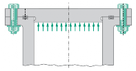
Wall Thickness Calculation of Flat Head Under Internal Pressure
Spreadsheet calculator as per:
ASME Section VIII Div 1 - UG 34 - Unstayed Flat Heads and Covers
TEMA RCB 9.21 - Flat Channel Cover Deflection - Multipass Units

Thickness of Shells and Tubes Under External Pressure
Spreadsheet calculator as per Section VIII Div 1 - UG-28 - Thickness Of Shells And Tubes Under External Pressure.
- Spreadsheet for Training Use (SI Units)
- Spreadsheet for Training Use (US Customary Units)
- Spreadsheet for Professional Use (SI Units)
- Spreadsheet for Professional Use (US Customary Units)

Wall Thickness Calculation of Heads Under External Pressure
Spreadsheet calculator as per Section VIII Div 1 - UG 33 - Thickness of Formed Heads, Pressure on Convex Side.
- Spreadsheet for Training Use (SI Units)
- Spreadsheet for Training Use (US Customary Units)
- Spreadsheet for Professional Use (SI Units)
- Spreadsheet for Professional Use (US Customary Units)

Nozzle Neck (Thickness and Reinforcement)
Spreadsheet calculator as per UG-45 Nozzle Neck Thickness and, UG-37 Reinforcement Required for Openings in Shells and Formed Heads.
")
The compressibility factor (Z), also known as the compression factor or the gas deviation factor, is a correction factor which describes the deviation of a real gas from ideal gas behavior. It is simply defined as the ratio of the molar volume of a gas to the molar volume of an ideal gas at the same temperature and pressure. It is a useful thermodynamic property for modifying the ideal gas law to account for the real gas behavior.